Structural elements of the steel hall
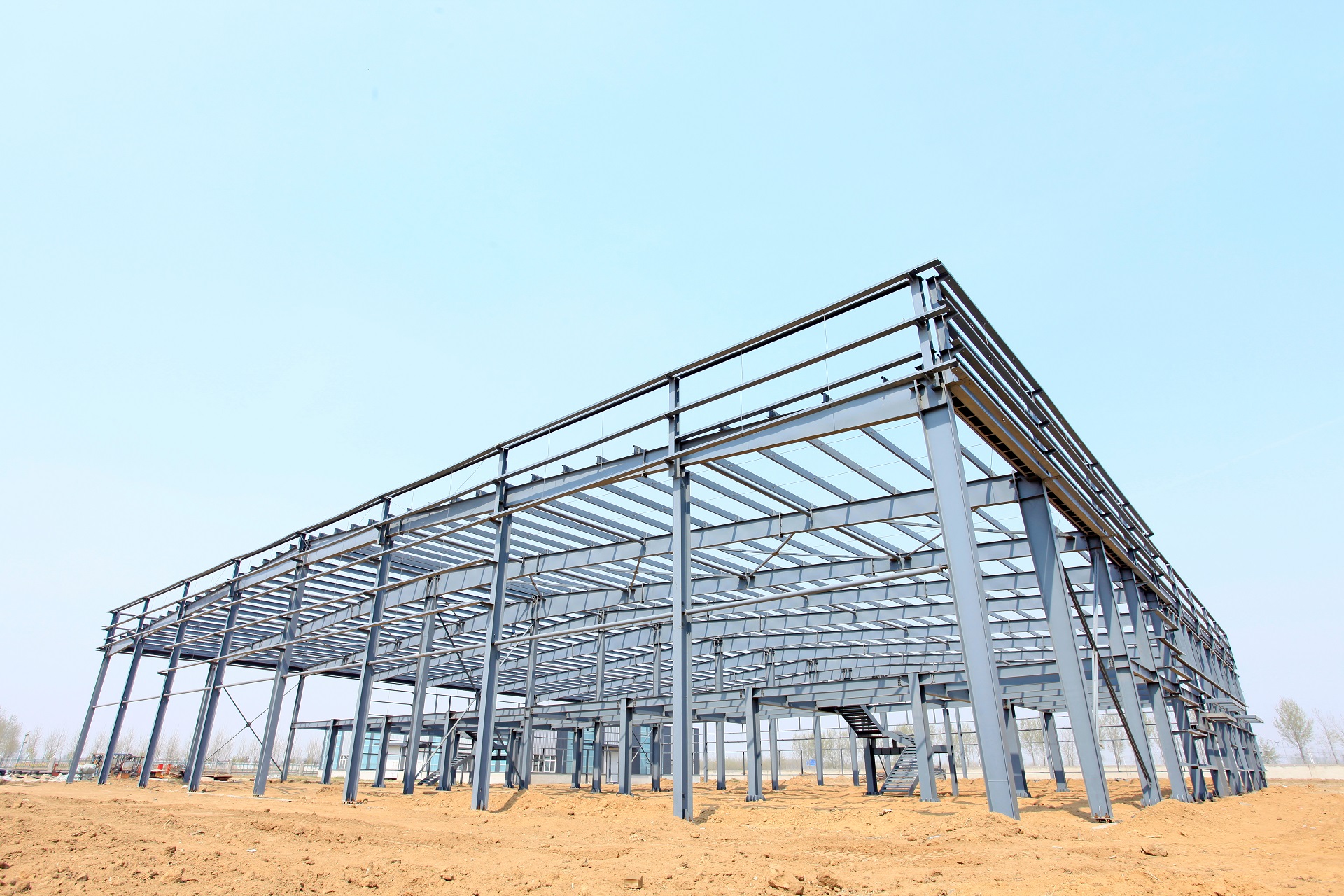
Steel halls are one of the most popular industrial building structures. For this reason, the structural elements of a steel hall are very well studied and described broadly in literature, allowing their load-bearing to be optimised. Steel hall components can be divided, quite conventionally, into two groups in terms of the role they play in the structure:
- primary structure (columns and main rafters),
- secondary structure (purlins, bracing, gable wall columns, transom structure).
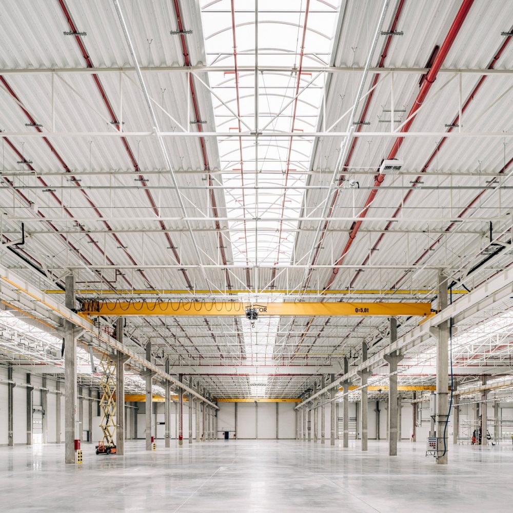
The load-bearing structure of a steel hall is in most cases a flat-frame structural system. The hall is created by duplicating the aforementioned frame several times in relation to its longitudinal axis. Each frame consists of main columns that support the main roof girders. Halls can be single or multi-storey, single-aisle or consist of several aisles which, of course, affects the number of columns and rafters.
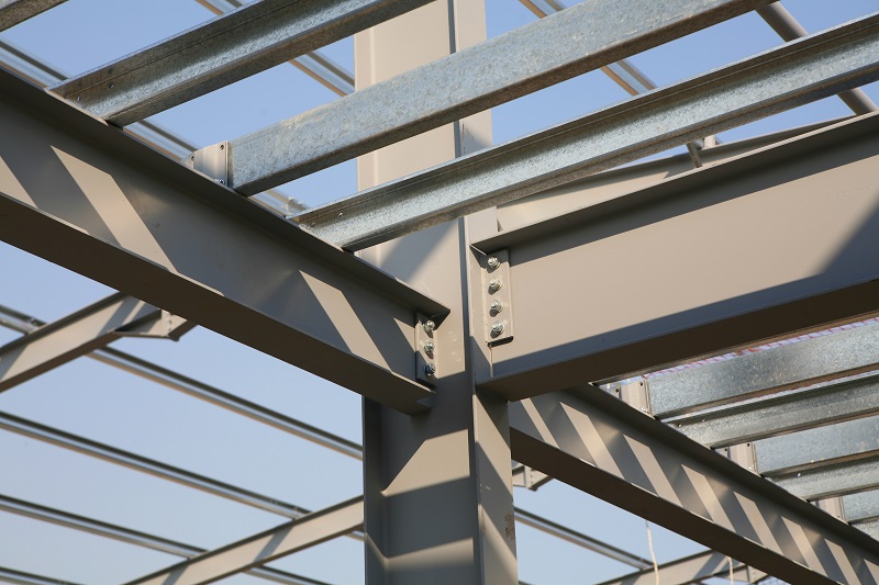
The columns have articulated joints with the foundation, or more precisely, articulated joints on the footings using steel anchors. The rigidity of the frame is ensured by designing a rigid corner (the connection point between the transom and the column). This causes the frame system to be stable (steady) in its plane. When it comes to selecting steel mullion sections, there are several types of solution to choose from. These elements can be made of hot-rolled sections (IPE, HEB, HEA) or welded sheet metal. Both solutions have their advantages and drawbacks. The advantage of the first approach is that the components are purchased as finished products, but the use of steel is less efficient. The use of plate girders (of fixed or variable cross-section) has to take into account the costs resulting from the time and labour required to produce them. What you get in return, however, is a near-optimal component in terms of steel efficiency. It is reasonable to design the columns of the main structure from S355 steel.
The basic yet obvious role of roof girders is to support the roof layers and to transfer loads from wind, snow and process loads. These can be divided into two types. The first type is full-wall transoms, i.e. beam hall elements made of either hot-rolled sections (IPE, HEB, HEA) or welded elements known as sheet metal. S355 steel grade is used. Its cost is about 10-15% higher than that of S235 steel, while the gains in load-bearing capacity can reach 30-40%. Plate girders can be designed as beams with a constant section depth or with a variable depth (so-called converging web beams). The choice between a rolled beam and a plate girder is determined by its span and the loads assumed. For a typical steel hall with a column spacing of 12-16 m, a hot-rolled section transom would be a suitable solution. On the other hand, if the roof is heavily loaded and, in addition, the span exceeds 16-18 m, then the designer should consider using a welded section. This structure, thanks to its free-form geometry (beam height, thickness and width of chords), can transmit very high internal forces within the frame. Of course, it is important to realise that steel plate beams have to be individually made in a fabrication shop, which makes them longer and more costly to produce. Using hot-rolled sections is simplified in that they only need to be cut to length and drilled. The second type of superstructure is truss girders. These elements can be used in halls with column spacings exceeding 20-24 m. This is the conventional span above which the use of a truss is a lighter solution than a solid-wall beam. Important from the point of view of the volume and the functionality of the hall itself is the height of the truss. It is usually taken in the range of 1/10-1/12 of the span. Therefore, for a hall with a column spacing of, for example, 24 m, it should be anticipated that the truss will “consume” about 2 m from the space under the roof. At the same time, such a significant height increases the rigidity of the structure and reduces roof deflections. A more detailed description of trusses can be found in other studies – Investor guide.
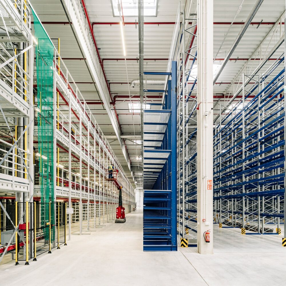
Roof purlins are another important element of a steel hall. They provide the foundation for the roofing elements (trapezoidal sheet metal, sandwich panels). The purlins can either be laid on the roof girders or span between them. They can be designed as continuous beams, multi-span beams as well as free-supported beams. If the frame spacing is less than 8 m, then the purlin can be made of IPE or HEA hot-rolled sections. If the purlin is to span 8-15 m, then these elements are made as trusses. Their forming differs significantly. Square tube sections, round tube sections, I-sections (usually HEA) can be used. A truss structure, with significant spans, will always be a lighter solution than a rolled or welded beam. Steel hall elements are now being designed in such a way that material consumption per m2 is as economical as possible. The use of purlins made from cold-formed sheets (Z sections, channels, sigma sections) allows the weight of the structure to be significantly reduced. However, it is more expensive and requires more calculations at the section selection stage. Some simplification and convenience is provided by calculators or tables offered by manufacturers to select the right section. Steel with a yield strength of 355MPa (S355) or S350 in the case of cold-formed sections is used.
It was mentioned earlier that the stability of the main frame of the steel hall is ensured by using a rigid connection at the corner while articulating the columns on the footings. It is worth asking what provides rigidity to the frame from its plane? In other words, what causes the main frame to remain upright despite the articulated support on the footings? The elements responsible for this are the wall bracing system, the roof bracing system (the so-called transverse slope brace) and the vertical longitudinal braces. These are steel hall elements usually made in the shape of an “X”, located in the pre-frame fields of the hall (between the second and third frames counting from the ends of the hall). In most cases, these are made of D12÷D30 solid bars, which can only transmit tensile forces. For this reason, it makes sense to make them from S355 steel, which has precisely the higher tensile strength than, for example, S235 steel. Storage halls and production halls are often equipped with overhead cranes or cranes suspended from the roof structure. This is due to the need to transport stored components, manufactured goods or repair heavy process equipment that needs to be dismantled and sent for servicing. During the repeated passes of the crane along the hall, dynamic loads are generated, causing changes in the stresses in the hall structure. For this reason, the bracing in such halls is made of bars that can also transmit compressive forces in addition to tension. In such situations, square tube or round tube sections are used. This eliminates the need for frequent tensioning of the flaccid bar bracing made of solid bar. A more detailed description of the steel hall bracing system can be found in the Investor Guide. Considering the overhead cranes and internal handling, mention should be made of elements that are not always present in a steel hall, namely the crane beams on which the crane moves (if present). They are generally single-span elements with a free-supported beam design. They are made from HEB or HEA wide-roof sections and, for higher crane capacities, also from welded I-sections. S235 steel can be used because, due to the static scheme, it is usually the deflection of the beam that is decisive and not its load-bearing capacity.
Gable wall columns are vertical elements located in the extreme frame of the hall. At the base, they are articulated at the footings and their apex is also articulated to the roof transom (the so-called wishbone column). These elements play several important roles in the design. They support the gable wall rafter, which results in the gable wall rafters having the static scheme of a multi-span beam and therefore can be made of much smaller sections (usually HEA) than the rafters of the more heavily loaded internal frames. In addition, the columns of the end frames take up the load from the wind blowing on the gable wall (wind pressure and wind suction). They also act as support for the hall shell. Gable wall columns are usually designed from hot-rolled HEA sections in S235 or S355 steel.
A transom structure is a steel hall element made of square or rectangular tubes, located between the main frames and between the gable wall columns. They are used to support the hall cladding (mainly with vertical cladding), but also as supports for wall, door and gate framing. These components are made from S235JR steel. For this group of components, there is no need for higher steel grades, as their load-bearing capacity is usually not heavily utilised.
All of the aforementioned elements are prefabricated in the steel construction factory and then transported to the construction site as so-called ‘shipping elements’. A hall made of prefabricated shipping elements can be assembled in a very short time, using screws, and thus quickly put into use.