BIM (Building Information Modelling) – what is it?
BIM or Building Information Modelling literally means modelling information about a building. The question that arises intuitively is about what information is modelled and how this information can be used. This article explains what BIM is, its main assumptions, objectives, capabilities and requirements for the user of this relatively new, but very rapidly developing technology.
BIM is a new, digital approach to the project completion process at every stage from the concept, through the building design development, its use, until the very end of its life, i.e. the demolition. We all know the problems that lie in the natural need to exchange information between the actors involved in a project. We are often faced with design errors and clashes from insufficient cooperation between the architect and the designer, or the designer and the installer. These often involve lost time and, thus increased overall project cost. With BIM, these issues are avoided or at least they are made less likely to occur. This is made possible thanks to the main premise of BIM which is simultaneous access to the BIM model created by all stakeholders. Typically, a BIM model is created on a main server or stored in the cloud which allows cross-industry, instant access to the data it contains. All model data is updated in real time. This way, changes made by e.g. the architect are visible to the investor, constructor or process engineer. Continuous access to up-to-date data in the BIM model makes it possible to address issues quickly and make project-related decisions. BIM design is not only a 3D spatial model, but also a time-sensitive model of the entire project. The model created can take into account the time needed to deliver the raw materials, the time for prefabrication, to assemble the structure or the time it takes to finish the work. Therefore, the BIM project is also some kind of a work schedule. Another advantage of BIM technology is the ability to automatically create all kinds of lists, statements, reports, cost estimates, lists based on one common model. These types of documents are based on databases that are included in the model, or more precisely, in its components. Each element of the model is described by its properties. Databases enable fast and precise filtering of the model and finding objects in it. You can assign names to such components as columns, main beams, windows, doors, lintels, pipelines, supports, etc., so as to create ‘families’ of objects. A huge number of variables is involved here. In addition to basic characteristics such as length, width, material, cross-sectional features, net or gross weight, more sophisticated values (thermal resistance, flame retardant properties of the material, tightness, painting surface of the component) can be assigned. It is this variety of data and the different levels of detail in the BIM model that forms the basis for the qualitative classification of each BIM model. It is based on the level of development (LOD). The 6 degrees of model deployment are briefly characterised below:
- LOD 100 is intended for a basic or conceptual design. The elements of such a model are presented in a general and symbolic manner. The data provided include the area, height, location, orientation of the object in question at the site.
- LOD 200 corresponds to a schematic model. Elements are presented by means of a symbol or a general solid, making it possible to determine the volume. This degree of deployment makes it possible to make functional-utility adjustments.
- LOD 300 is an accuracy close to a building permit design, as the elements enable initial counting and measuring. The elements are already represented as the specific structural components.
- The LOD 350 builds on the detail of the LOD 300 with the joints, supports and clear descriptions. It corresponds to the detailed design.
- LOD 400 is used during the construction phase by the contractor. Components are modelled as detailed assemblies with full manufacturing, assembly and fabrication details. The model provides details sufficient to make accurate calculations of quantities, sizes, shapes, weights or orientation on site.
- LOD 500 is suitable for the as-built documentation. The elements are modelled by reflecting their actual execution on site. The data contained in the model is used for maintenance and operation of the facility once it has been built.
A key issue in creating a BIM model is parameterisation. What is it? What is it for? Why is it so important? Parameterisation is a combination of a geometric model with a logical mathematical model. Since a geometric model is actually a set of points whose graphical representation can be viewed on a monitor screen, they can be assigned conditions to interact with. This refers to the geometrical dependence (perpendicularity, parallelism of surfaces) and dimensional dependence (width, length, height of the element). The user defines the object features to achieve, selects the input geometric elements (beams, walls, floors) and specifies the parameters describing the output geometric effect. This can be easily described on the basis of parametric modelling of a stair flight. In the model, the levels to connect the flights (entrance elements) are selected. Then, parameters such as the flight width, step height, the profile of the joists, etc. are specified. Once the initial and final levels are specified, the flights mentioned with predefined properties are automatically added to the model. So parameterisation undoubtedly speeds up the BIM modelling. A definite advantage of parameterisation is that changes are made automatically. If, as in the above example, the flight level is changed, the application itself adjusts the number of steps and the length or angle of the stair joists. It is of course possible to save parameterised settings for use elsewhere, at a different place and time in the model. A BIM system is therefore based on the interaction between the user and software.
Check out our range of industrial construction projects
BIM technology in construction industry
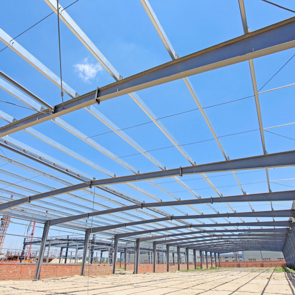
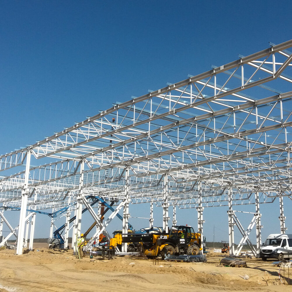
Construction is an industry that is very active in using BIM technology which can be seen from the conceptual design stage, through detailed design, installation, as-built design and the use of the building. The joint management of the model by architects, constructors and installers has tangible, already mentioned, advantages. Architects have extensive libraries of furniture, plants, vehicles, fittings or decorative elements that enhance the presentation of the project. Thanks to parameterisation, they can easily model the object and its surroundings. For example, the user selects the wall on which the doors or windows are to be located, provides their dimensions and the software automatically inserts these objects into the model. Of course, lists (e.g. of joinery or flashings) are also produced automatically based on a common model. The currently used BIM technology in design is particularly helpful in the work of the designer and engineer. The detailed model makes it possible to obtain almost immediately workshop drawings of steel, timber or reinforced concrete structures. The continuously developed, parameterised libraries of connections and even entire steel or reinforced concrete components allow you to forget about archaic 2D CAD drafting. Parameterisation in the work of a designer is particularly prominent. For example, when designing the base of a steel column, it is sufficient to indicate the column in the model and specify the number and size of anchors, their spacing and depth of anchorage and the program will automatically insert into the model the geometric response to the user input. Of course, there are endless examples of parameterisation. Since the user can create new parameterised objects themselves, it can be said that only imagination limits the use of parameterisation in BIM modelling. Ready-made gratings, steps or floor slabs are inserted into the models with just a few clicks. Technology backgrounds in IFC, 3D DWG or DGN formats allow you to design the course of the installation without any collision with structural elements. CNC (Computerised Numerical Control) files are already widely used. These are text files that contain digital information about the geometry of steel components (shape, length, holes in plates). These are forwarded to the steel construction plant and, based on them, machines automatically cut out the necessary components. This can be said to be a sustainable measure, as it makes it possible to avoid printing part of the design documentation. The BIM model is particularly useful during structural assembly. You can easily and quickly determine at what place of the construction a given element is to be located. You can read out information on the size and class of bolts to be used to bolt the steel components together. The LOD 400 grade models assist the contractor in selecting the crane, as they can determine a suitable location for its erection and establish the dimensions and weights of the various lifting elements. Certainly BIM construction will continue to be developed. New BIM modelling software is emerging on the market. Moreover, software compatibility is an important aspect which is also a challenge for developers. This is particularly important because there are programs designed for static-strength calculations or visualisation, while another group are programs designed for BIM modelling. That is why it is so important to develop a file format that enables seamless data exchange. Currently, the most common format for file sharing is IFC (Industry Foundation Classes). It is popular as a neutral format that allows precise transfer of BIM model data. The current version is IFC 4, in use since 2013. The next version, IFC 5, is currently under development.
The topic covered in this guide is very broad and innovative. There is no doubt that familiarity and proficiency with BIM modelling technology is the future of the industry, not just construction, and will be an indicator of attractiveness to investors and employers.